
Visual Docking Guided System
GIS206-2
- Introduction
-
- Docking can be accomplished by either the pilot or the copilot.
- Alert is given if the aircraft approaching the gate is not the aircraft type set to be docking.
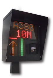
- Large 8 inch highly visible alphanumeric display for the pilot and the copilot.
- The familiar azimuth bar display format is used featuring large 12 inch high azimuth bars easily visible to both the pilot and the copilot.
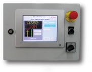
- The operator interface uses a full graphic display for the clarity of the information presentation.
- Optional multiple operator interface points per gate.
- Optional host computer communication option for reporting and control.
- Optional dead-man switch on operator keyboard.
- Optional lockout input in the case that the passenger loading bridge is not parked.
- Optional lockout output to prevent the passenger loading bridge from moving until the aircraft is docked.
- Compliance to ICAO Annex 14 recommendations.
- Components
-
Components
RLG GIS206-2 System Standard Components:
A one line alphanumeric display, 5 characters. Range finder laser with two axis scanning. Operator keyboard and control CPU unit.
RLG GIS206-2 System Options:
- A second line alphanumeric display, 5 characters.
- Real time display.
- Multiple operator keyboard control points per gate.
- Communication with a host computer.
Compatible with all RLG models. Software, central and gate network interface devices, PC, color monitor, laser printer for communication from gate to terminal control or maintenance center to control or monitor gates and indication of gate occupancy or availability for traffic and data such as time on gate, system condition, etc. System ability to interface with CUTE, FIDS, BMS or others.
- System Overview
-
System Overview
The RLG GIS206-2 Laser Guided Docking System safely guides the parking aircraft to the precise parking position dictated by the terminal authority. The use of a a two axis scanning range finder laser allows the RLG GIS206-2 to present the parking information to both the pilot and the copilot simultaneously. Since the azimuth display is electronically controlled (rather than optically fixed) the information gathered from the laser scanner is presented in a display that can be readily read by either the pilot or the copilot such that either can dock the aircraft.
Further, the RLG GIS206-2 compares the features of the aircraft that is approaching the gate to a stored database of various aircraft types and alerts the pilot, the copilot, the gate personnel, and the host computer (if one is utilized) when the aircraft approaching the gate is physically inconsistent with the selected aircraft type.
- System Installation
-
System Installation
The GIS206-2 main enclosure is attached to the terminal building or other support precisely lined up with, and perpendicular to, the extension of the aircraft J line or center line as that line would approach the terminal building or support. This aligns the laser portion of the RLG GIS206-2 with the azimuth center of the parking aircraft. The height above the tarmac should be determined such that the seven inch high alphanumeric display and azimuth display will be at a height for comfortable viewing by both the pilot and the copilot whether in the shortest or the tallest aircraft that will be parked.
After the RLG GIS206-2 is physically secured there is an electronic calibration procedure to ensure that the system will give the best possible performance. This results in the RLG GIS206-2 guiding the aircraft to a parking position where the nose wheel is within a six inch radius of the terminal authority dictated parking position.
- System Use Detail
-
System Use Detail
The RLG GIS206-2 Laser Guided Docking System is a fully automatic aircraft docking guidance system for various types of modern aircraft.
The system utilizes 2-axis laser scanning technique to track both the lateral and longitudinal positions of the incoming aircraft and guide the aircraft to the programmed stopping position. In addition, the system also has aircraft ID verification feature (OPTIONAL) to identify the incoming aircraft and check it against the one selected by the operator. If the incoming aircraft fails to match the expected aircraft, an ‘ID FAIL’ indication is immediately issued via display information console to both the pilot and the co-pilot.
Aircraft type, continuous closing distance, and azimuth guidance, etc, are presented on a single console clearly visible to both the pilot and co-pilot, simultaneously. Figure A shows the Aircraft Display console, mounted on the terminal in front of the aircraft stand.
The system is operated only in the automatic mode. If the system fails, the aircraft must then be marshalled into the stand manually.
- Specifications
-
System Power AC Input: 85~240V, 50Hz~60Hz, Auto Select. < 60 Watts. Laser Category FDA CDRH Class 1, Eye Safe, 905nm Horizontal Scan + /-15 degrees Vertical Scan +20 (up) / -25 (down) degrees Range 150 meters Range Accuracy 0.2m at 150 meters; 0.1m at <50 meters. Azimuth Accuracy 0.2 degrees Stop Position Accuracy 0.1 meters Operator’s Panel Dimensions 540 mm x 440 mm x 250 mm Operator Display Type Color LCD Touch Panel Operator’s Panel Interface Serial Communication RS 422/485 Display Character Height 202 mm Display Visibility Distance > 100 meters Color of Display Board Black/Green PC connectivity for maintenance TCP/IP 10/100 Base T Display Console Dimension 1020 mm x 1061 mm x 350 mm Display Console Material Aluminum Display Console Weight App. 60kg (including Laser Unit) IP level IP54 System Operation Temperature -10 ºC~ +55 ºC System Operation Humidity 5% - 95% (non condensing)