
Visual Docking Guided System
GIS206
- About GIS206
-
About GIS206
The RLG Model GIS206 is a single axis Laser Guided Docking System that complies with ICAO Annex 14 recommendations.
RLG GIS206 System Overview
Parking tolerance to loading bridge with aircraft having pilot tubes forward of the passenger doors is extremely critical. The RLG System holds a tolerance of plus or minus six inches.
- Construction
-
Construction
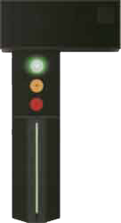
The RLG System consists of a metal enclosure housing attached to the terminal building or other support precisely lined up perpendicular to and twenty-one inches (.533M) left of the aircraft J line or centerline -- this dimension aligns to the center of the left hand pilot seat. The bottom of the enclosure housing contains three neon tubes -- a green tube flanked by two red tubes. The green tube is encased in baffles, the red tubes are behind flanges so as to not be visible straight-on. When the pilot is taxiing in and can see only the green tube, the aircraft is in a correct centerline position -- plus or minus three inches. If a line of red is visible on either side, the aircraft is off line in that direction.
The upper part of the enclosure housing contains digital aircraft indicators -- 747, MD11, 340, etc. -- all aircraft types as required for a particular position for that aircraft mix and to indicate closure information by meters or feet and "STOP" as the aircraft reaches parking position. This part of the housing may, as mounting requires, be located to the side of the light housing.
- Display
-
Display
The LED display below the aircraft indicator -- top, green -- center, yellow -- bottom, red -- functions as follows: green, indicating laser scanning acquisition and tracking -- yellow, indicating caution during closure readings -- red, STOP. As each color is activated, the other color automatically turns off.
The laser scanner/microprocessor housing is located on the aircraft centerline to receive landing information and automatically preset the tracking height and the horizontal scanning range according to the centerline. After receiving the information, the system confirms the data and displays it on the aircraft indicator.
GREEN
Light Housing Gate Clear
--Aircraft off centerline to left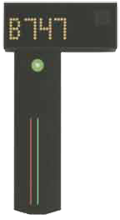
YELLOW
Caution 10M (32 ft.) to stop
--Aircraft off centerline to right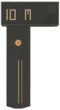
YELLOW
Display Countdown to 1M (6ft.) to stop
--Aircraft on centerline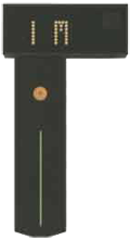
RED
STOP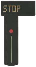
- System Operation
-
System Operation
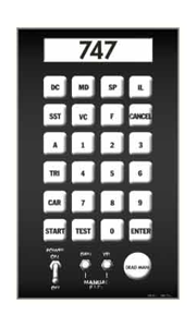
The control unit is turned on by activating the POWER ON and START switches on the control panel on the control box at the ramp's base or, as an option, in the bridge cabin (in this case, the emergency stop switch on the ramp will override bridge control). After proper arriving aircraft has been selected and system test procedures have been followed, the system is completely automatic. Lights on the control panel and LCD screen will monitor the aircraft indicator and light housing.
When an aircraft arrives at the beginning of the centerline, the laser scans and acquires the nose of the approaching aircraft and commences tracking. The acquisition of the aircraft is tracked until the final stop.
After acquisition, the docking system measures the distance between the laser head and the nose of the aircraft. Throughout the docking process, the communication unit calculates the closing rate information and displays it on the display unit, enabling the pilot to properly dock the aircraft. The RLG System can accommodate two or more separate centerlines with a single control box if a loading bridge is not versatile enough to service wide and narrow body aircraft on a common centerline, or with inflexible fuel pits, or to accommodate wide/narrow body aircraft types at adjacent gates.
- Safety Features
-
Safety Features
An emergency stop swtich on the control panel overrides circuitry activating the stop lights. Manual switches are on the control panel for remote or temporary parking positions. "Dead-man" switch is optional and recommended.
Additional "fail safe" devices have been incorporated. There is an electronic timing circuit to deactivate the system ten seconds after the stop light is illuminated. A malfunction search system monitors the system and deactivates the entire system in case of a malfunction (examples: lamps fail, circuit failure, power failure, etc.). Pilots are instructed that this means STOP. A printed circuit check system has been included which will automatically check system controls and show conditions with inidcator lights on the control panel.
Remote control/monitoring in ground operations is optional with a hook-up to FIDS systems. The RLG System is all-weather for any climate. Existing GIS203 and GIS204 systems -- over 900 installed worldwide -- can be updated to GIS206 with the addition of laser scanner/microprocessor, utilizing existing light housings, aircraft indicators and control boxes with minor alterations.
The GIS206 interfaces with the GIS205 Microprocessor Based Airport Gate Controller and Guide-In System allowing for centralized control and networked operation. Existing GIS204 and GIS204-3 units can be easily upgraded to the GIS206.
- Specifications
-
Specifications
Power - 100 VAC to 240 VAC 50-60Hz universal input, 200 watts
- AC power UPS system optional
Laser - Category: Class I, eye safe
- Range: 150 meters minimum
- Accuracy: 0.5 meter at 150 meters, and 0.1 meter at 50 meters or better
- Scaning: +/- 45 degrees vertical
Reliability - MTBF: 5000 hours
- MTTR: Variable based on the spare parts kit purchased.
Central Control - Work Station: PC based
- Communication with gates: 10/100 Base T, TCP/IP
Physical - Keyboard control unit: 8 inches wide x 6 inches high x 12 inches deep
- Aircraft indicator/laser housing: 38 inches wide x 16 inches high x 12 inches deep
- Light Housing Display: 56 inches high x 14 inches wide x 18 inches deep